Diffusing Hands

A play on “Drawing Hands” by M.C. Escher
https://en.wikipedia.org/wiki/Drawing_Hands

Why?

There’s been a lot of negativity towards “AI Art”, especially from the “traditional” art community.

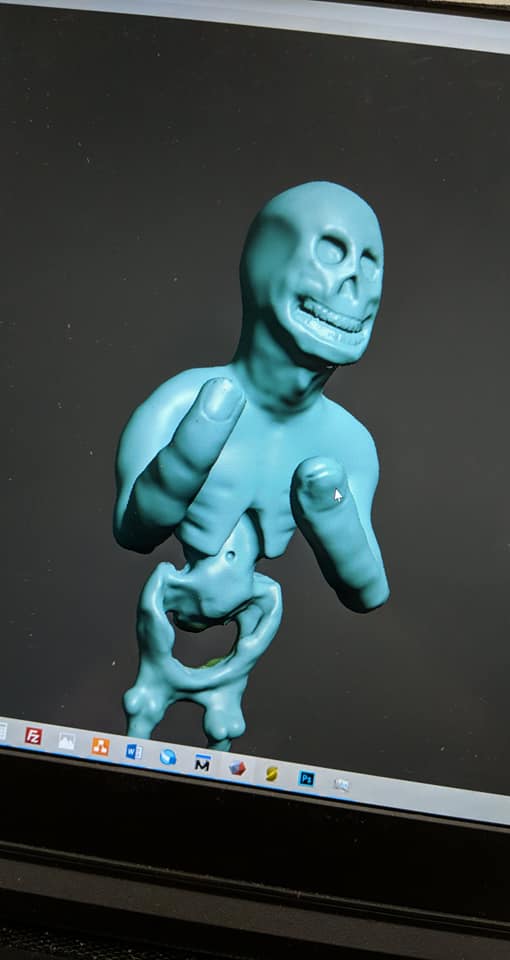
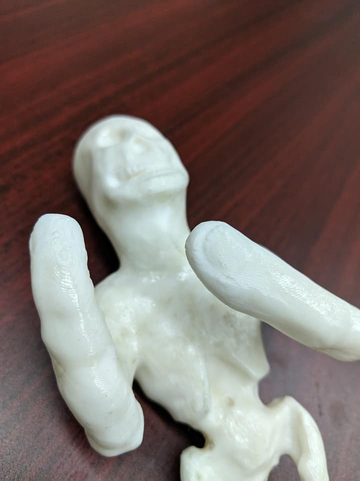
Most people think of “AI Art” as a one-click one-and-done workflow. You type a prompt, hit “generate” a few times, and voila! This may be true in certain cases, but you’ll end up with some wonky results:

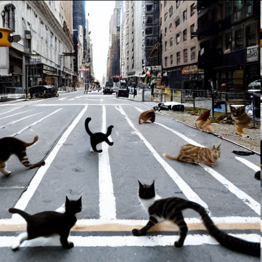
Sure you can fiddle with the prompts, click “generate” a hundred times until you get the perfect result.

I want to show that AI art can be worthwhile, and a useful tool, for bringing concept to image.

How?

You can get extremely granular control of image generation by using a few techniques, such as img2img in-painting, or manually seeding the image in your favorite image editing application. In this example, I wanted the output to be purely generated by AI. However, I’ve had great success by manually manipulating or painting low-res features, then in-painting them to completion.

Much like a painter’s workflow, i.e. sketch, add the base colors, shading, add detail, this will be a very iterative process.

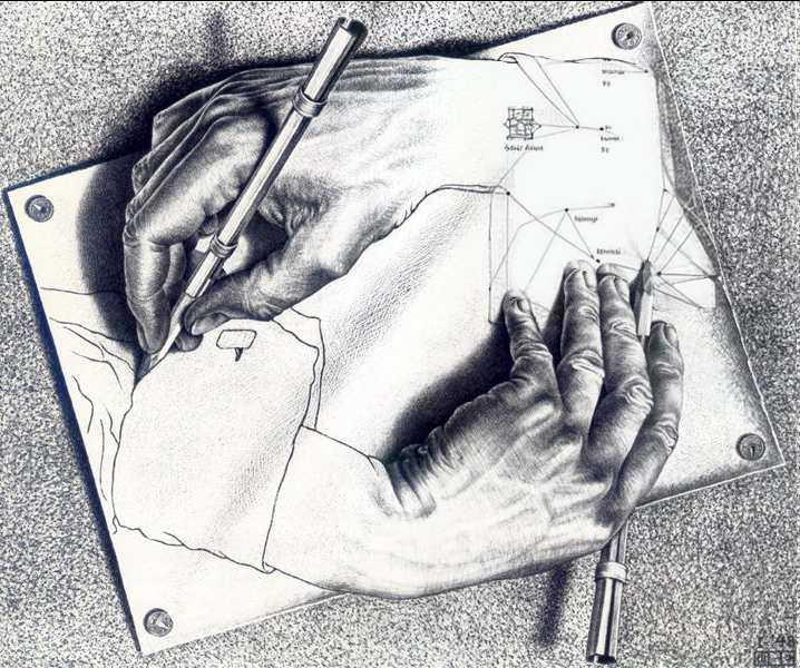
1: The starting point

I knew exactly what I wanted the final image to look like. Since this was a remix/parody/commentary, I started with M.C. Escher’s famous work.

Maybe I will do a write-up on starting from scratch in the future.
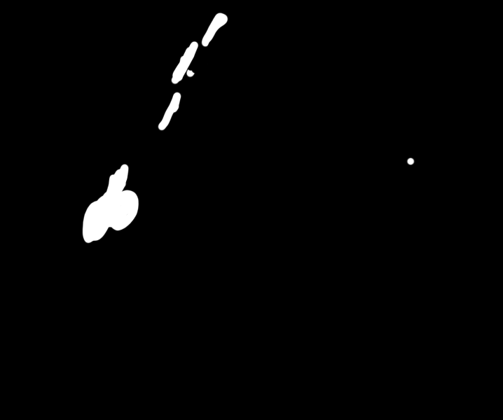
2: Masking

The most important part of the process is making a good mask. This is easily accomplished in Photoshop.

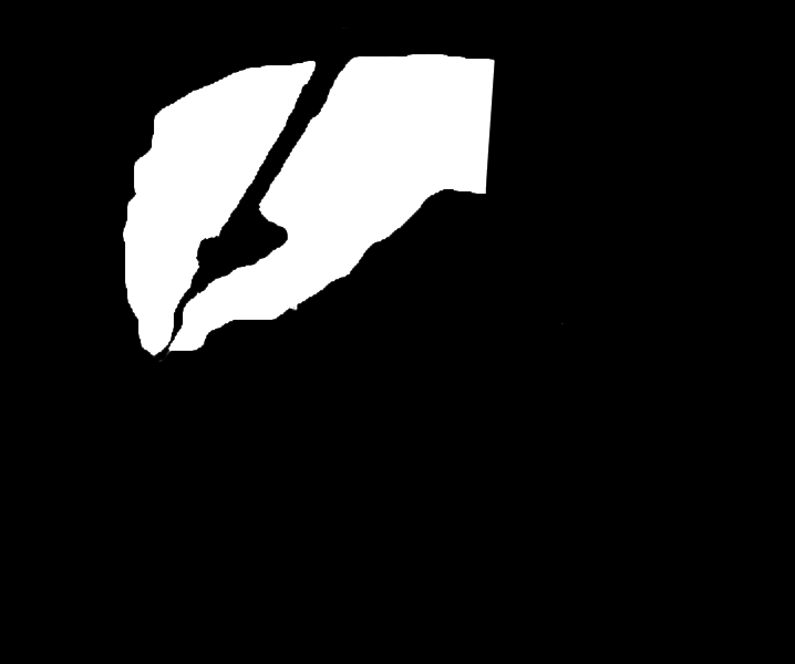
Once you have a good mask, you’re almost there.

Hitting “generate” a hundred times can work, but you might not get the “feel” you want. Also, in my case, the generated hand was kind of wonky and definitely did not fit the style of the work.

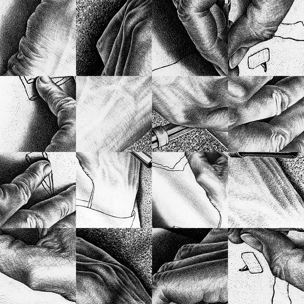
3: Training with Dreambooth

To get the pencil style of the work, we can zoom in and crop out pieces of the drawing. Zoom in too far, you’ll only have noise. Don’t zoom in enough, the concept learned will be the hands and pencils in the drawing. Took 3 times to get this right.

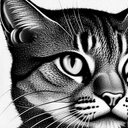
I used Dreambooth with the standard recommended settings. ~100 steps per image. I used 24 images and got decent results. Here is a cat in this style:

I used a similar process to get the style of robotic hands that I wanted, as well as the abstract drawing of the network/schematic/math. Took about 30 images of robot hands, and about 100 images of network architectures from various papers on AI.

4: Generate an Output

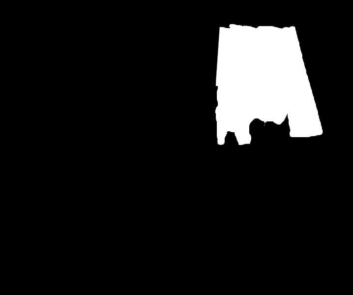
I started with the sleeves using an in-paint mask. I used “original” as the masked content fill method, 30 steps with Euler a, low CFG scale, and a denoise strength of about 0.3. I wanted the AI to retain the rough shape of the sleeve, and keep the relative level of detail to be low, to match the sketched sleeve.

Using the second mask with the hand,

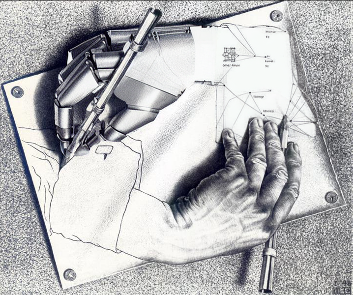
I was pretty happy with this result. However, there are a few imperfections. Like any art process, this is iterative. You won’t get perfect results first try.

Look at the fingers. Look at the pencil. The style could be a bit better as well.

5: Mask, Generate, Repeat

It also took some manual fixes. The clone and smudge tools in photoshop are a good way to reshape things. The AI will recognize the texture is supposed to be part of the object you’re filling in. Masking was used to retain the sharp point of the pencil. I had to manually straighten the pencil as well.
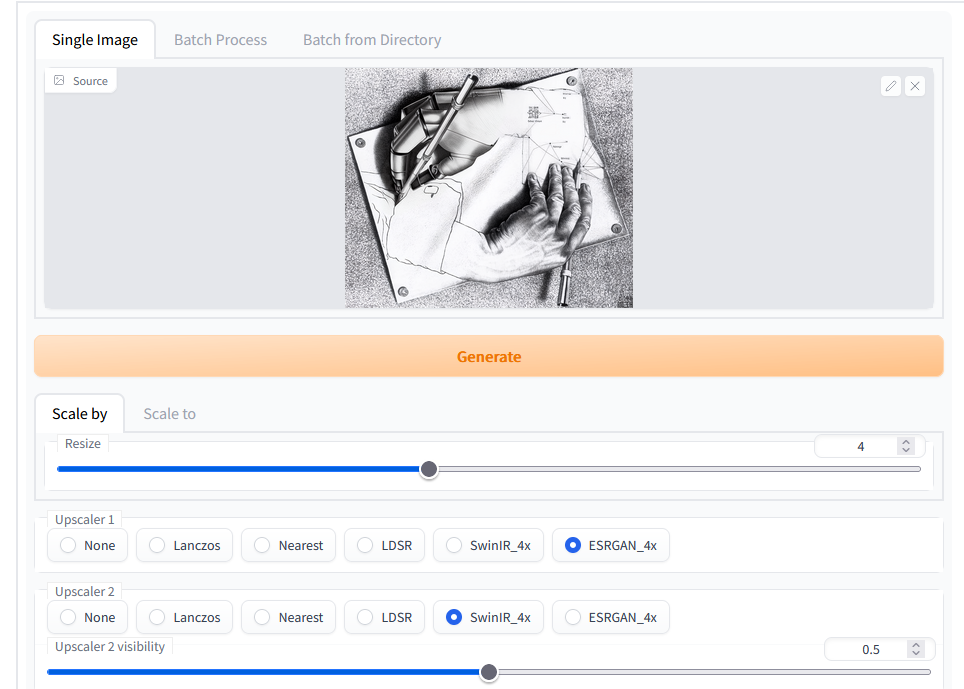
6: Upscale

I had the best luck using a 50/50 of SWINIR and ESRGAN. Using one or the other resulted in some parts of the piece being extremely sharp, others being blurred or distorted.

7: Done

A play on “Drawing Hands” by M.C. Escher
https://en.wikipedia.org/wiki/Drawing_Hands

Old Projects From The Past Few Years

I’ve made a lot of projects over the years, and I really haven’t captured them in a good, meaningful way. I’ve been intending to write up these projects for years now, but I just don’t have time time to dedicate a whole post and write-up to each project. Instead, I will post pictures of each project and do a mini-writeup for each project.

Circuit Board Christmas Tree

Instead of a Christmas card, This year I wanted to create something fun to give to family and friends.

I created the outline of a tree in adobe illustrator, exported this shape into KiCad. The ornaments were 3D printed and hot-glued together.

The circuit uses an Atmel AT-Tiny chip, red, orange, and green, LEDs, and a lithium cell for power.

3D Printing Brains

My girlfriend Sarah is a Neuroscience PhD student, but we met in the UWM Makerspace lab! She was giving a presentation on Alzheimer’s Disease and wanted to have a 3D print of her brain to pass out to the audience, for reference.

We took the raw files from an MRI she had gotten for research, processed the DICOM files, and converted these into a STL format file for 3D printing!

Antenna Theory Class Project: Hybrid Bi-Quad Yagi

In antenna theory class, the concept of the yagi was fascinating to me. How could passive elements increase antenna gain?! We ended up learning about this in detail, but I still had one question unanswered: is a yagi or log-periodic limited to only linear elements? Could this be done with loop antennas or other shaped elements?

The answer is, yes! I 3D printed wire-guides to hold magnet wire in the shape of a bi-quad antenna, and used these as elements. The antenna has a gain of 10.38dBi. The performance was comparable, but not better, than a traditional 4 element Yagi.

3D Sculpting:

I had gotten a drawing tablet and “space mouse” for use with CAD. These are both incredible tools. To try them out, and to get some practice in, I started with an avant garde art piece. This is “Mr. Bone Man”

I used the program “Mesh Mixer” which is an amazing piece of FREE software. While this demo piece is very silly and strange, the ability to sculpt smooth models is very powerful. I can forsee myself using this for ergonomic prints, for example, handles, grips, or other organic shapes.

Sewing Machine and Masks

I got this sewing machine for my girlfriend, right at the start of the pandemic. It’s an antique, so it took some work restoring it! I mostly worked to oil everything, clean out corrosion, replace broken parts like plastic spacers and springs.

Bonus picture: one of our first masks we made together.

Senior Capstone Project: EM Scanner

This is one project I’m particularly proud of. My team designed an EM field scanner, used for identifying the source of EMF noise and interference, particularly for pre-regulatory testing.

The project uses an RTL-SDR, software defined radio, to pick up the intensity of RF signal, while a CNC gantry moves the antenna around. The intensity of RF signal is mapped over X and Y space.

In the arduino example, the highest amplitude interference is around the crystal oscillator. In the wire example, a signal generator was used to feed current through a wire of arbitrary shape.

Keypad Molding Project

Long ago, I wanted to make a custom keypad device. To keep costs down, I wanted to use a rubber membrane type keypad, opposed to using (expensive) mechanical key caps. I CNC milled the mold out of aluminum and used silicone casting material.

Overall the membrane turned out great, however, I could not find a good way to keep the contact surface conductive. This project fizzled out, but I did prove the concept of making a custom membrane keypad!

Perceptron: Neural Networks Class Project

For my final project in Neural Networks class, I made a real-time perceptron for identifying numbers. It takes the input from an arducam module, python code was running on a raspberry pi.

Dart Parts on CNC Lathe

My friends and I love playing darts. One of my darts got stepped on and the back flight holder snapped off. While I was waiting for my replacement darts to come, I tried using a CNC lathe to make a part.

It worked okay, but largely was unbalanced. It was a fun idea though!

Aluminum Fidget Spinner

During the fidget spinner I used a CNC Mill to create an aluminum spinner. It turned out great!

Laser Cut Puzzle

Getting my feet wet with the laser cutter:

Baltic Birch Plywood pieces on a black ABS base

3D Printed Whiskey Glass Holders

I love whiskey, but whiskey glasses can take a lot of space up if they can’t stack. I came up with a simple print to allow me to stack them!

DSLR Photography Monitor

One of my first projects at the Milwaukee Makerspace was a DSLR photography monitor. Basically, a larger screen to view the picture on, so I can adjust focus and other parameters while the camera is on a tripod.

This project was heavily inspired (or copied 🙂 ) from William Osman, http://www.williamosman.com/2016/01/laser-cut-dslr-monitor.html

Steak Brand

A friend of a friend had a film project, and they needed a good way to brand a steak with the words “Flambe”, the title of the film. I learned a ton from this project, it was one of my first metal working projects ever.

Lessons learned: steak branding should be done with steel, super glue shouldn’t hold items that are HOT, and the brand should have been reversed.

Fixing a Megaphone

2020 has been a crazy year. Pandemic, Protests, Murder Hornets, and no end in sight!

I had joined a Milwaukee activism facebook group for donating supplies. One member had a megaphone to donate, but lost the charger!

I offered some of my time to fix it- either find/make a new charger, or find a way to make it run off of a common type of battery available at Walmart or Walgreens.

Buy Blue Ocean Megaphones at SWFA.com

First I checked online- is this battery common or cheap? How about the charger?

Nope! $100 for a charger! Not worth just buying one. The battery comes for around $100 as well, I could save $200 if I can fix this!

The first challenge was finding out the voltage and pin-out of the battery. That is, which is (+) and which is (-). It is a proprietary battery pack, and I was not able to find any information on it online.

So, I took it apart and took a look at the 4 battery pins on the circuit board.

Right away I saw that one pin was connected to the “ground plane“, I marked this in BLUE. Circuit boards start with a flat sheet of copper and etch away around wires and connections. In this case, most of the sheet has been left intact to connect all of the ground connections (-). In some boards there are also “power planes”, where the whole sheet of copper is left behind and connected to power pins.

Another way to find the (-) ground pin, I used my multimeter with the ohm (Ω) mode to measure resistance, and measured between each pin and any screw. The meter read 0.1Ω on this one pin, so this was it!

Next, I noticed that the two battery pins highlighted in YELLOW both connected to capacitors. To me this indicated that they were the communication lines, for the megaphone to check on battery status.

This left RED as the only pin left for (+). Unfortunately there was no way to check where this really connected, and I couldn’t remove the circuit board from the enclosure, as it was glued into place from the other side.

To test my hypothesis on which pins were (+) and (-), I ended up charging the battery slightly. It managed to hold a slight charge, and I was able to measure it with my multimeter on the VOLTAGE setting.

The side of the battery says “11.1V NOM”, which means the battery fully charged is usually around 11V. Batteries usually have a higher voltage when they are freshly charged, so this could be around 13V fully charged! And since batteries lose charge as you use them, this voltage can drop considerably. Half-way through a use, it may measure down to even 9V! So whichever battery solution I find, it had to be within 9-13V.

I then used a power supply to try powering it up. I used a lab supply, but anyone could use a “wall wart” supply, so long as the voltage matches.

Q. What's wrong with wall-warts?

9V worked! So I went ahead and ordered some 9V battery holders from amazon:

9V Battery Holders, Clips, and Contacts - MPD - Battery Holders, Clips,  Contacts | Online Catalog | DigiKey Electronics

And once it arrived I tried it out… It powered on! But when I keyed the siren key it would quickly die!

Shoot! 9V Batteries have a high internal resistance. That is, drawing lots of current, the voltage will drop considerably! And, a megaphone draws a lot of power!

While D-Cell batteries may provide enough current, but they’re only 1.5V! To get 9V I would need to stack 6 in series (“in a row”)! To get 12V I would need 8! Plus these batteries are HUGE and can be heavy!

So, I thought, what about a lithium battery? I have some very bright LED flashlights, they use lithium 123A batteries, available at your typical Walgreens or Walmart. These run at 3V and can supply considerable amounts of current!

6 pk 123 CR123A CR 123A 3V el123BP-6 Energizer Lithium Batteries -  TheBatterySupplier.Com

These actually fit my requirements perfectly- Small enough to fit in the battery slot, powerful enough to power the speaker and amplifier, and I should only need 4 (4x3V = 12V!). So, I went ahead and ordered some 123A battery holders:

So, I went ahead and soldered 4 of these together, then ran wire down to the battery pins and soldered them there.

Then, I used tape to secure everything.

It worked perfect! I finished taping it up, then lent it to some activist friends to use.

Reverse engineering a circuit to repair faulty boards

I was working on a personal project in the UWM Makerspace the other day, when Chris Beimborn, the Outreach Coordinater of the College of Engineering and Applied Science (CEAS), as well as the leader of a program called EnQuest, an Engineering program for high school age girls.

Over the past semester, they have been working on assembling Solar Panel stands and wiring up some cellphone charger boards for a project for a village in Guatemala. This mountainous village has no electricity, since the power lines were cut during a civil war. However, they still have a need for electricity, and cell phones for internet access. The area has cell phone reception, just no electricity. This is their means for communication with the world.

So, EnQuest was assembling these boards for the solar phone chargers, so villagers wouldn’t have to walk to the next village over to charge their phones. These chargers were then to be brought over by the UWM chapter of Engineering without Borders.

So, Chris comes to me asking if I could take a look at some boards. The boards were shipping out the next day, about about 10 of them weren’t working properly, as well as 2 solar panel assemblies. The SMD work was done by a group of volunteers who weren’t able to repair them in time, so I decided to take a look.

First I started with the datasheet of the only IC on the board, the TPS5516. Looking at the recommended schematic, I drew it out on a whiteboard. 

I then compared it to the printed circuit board I had on my desk, and annotated the schematic. I probed around with a multimeter. On some of the boards I was getting some odd readings, the V_Sense and V_Reg pins were reading the 5V but then the V_Out was reading 2.9V. The PG pin wasn’t on, so the power indicator light was off. PG ended up standing for “Power Good”

Probing around more, all of the other components were reading fine. I then decided to look under our microscope to see if I could find anything that was wrong with the soldering job. Immediately I was greeted with two mistakes notorious with SMD work.

Green: Solder bridging SMD pins

Red: Cold solder joint from hand soldering

So, pins were bridged on just about every faulty board. In addition, on half of these boards, the capacitor that controls the oscillation for the buck converter wasn’t even making contact!

After cleaning up the solder jobs and cleaning the flux off the board with isopropyl alcohol,  I was able to restore 9 out of 10 boards back to working order! The 10th board had a trace that was ripped off from thermal stress when the high-schoolers were soldering the large inductors on.

We were then able to package and ship them out, just in time for the Engineering without Borders team to take them to the airport.

Back at it with the SDR

My latest SDR project is a simple idea- a universal handicap door opening fob. The idea came to me one day, watching a lady in a wheel chair struggle to open the handicap door. She had to wheel up to the door, hit the button, wheel back, and then wheel forward through the door. And it took a good 10-20 seconds in the Wisconsin cold to wait for the door to open as well.

After witnessing this, every time I went through a building entrance, I imagined how someone with a physical disability might interact with the doors. And every time I noticed something that would really make entry a whole ordeal. It’s something that I feel engineers, building architects, whatever, just hadn’t thought about.

After about a week of making these observations, I started to notice the button placement, many times this box would be affixed to the side of a brick wall. And that got me thinking, “Do they really drill and run a cord through a block of concrete??” It dawned on me that it is actually a wireless transmitter and receiver!

So I broke out my RTL-SDR module and started recording. I used SDR# software to record the transmissions of 12 transmitters all around the EMS and Physics buildings. I ended up finding that it was an On/Off keyed signal, pretty standard and easy to work with.

The transmitters themselves are centered around 434 MHz, just like a car fob or garage opener. I found the frequency by using the FCC website, which contains a datasheet of every wireless transceiver in the US with FCC compliance. The datasheet of the transmitter contains the output power, the frequency, and other aspects that are useful for reverse engineering.

Picture of the transmission signal
Two of the recorded transmission signals

So, with the SDR#, I was able to record the audio of the transmitted signal, decoded from the carrier wave. Since it is On/Off keyed, the signal resembles binary. I thought it would be very inconvenient to make sense of 12 different signals like this, so I wrote a script in Matlab found here: https://pastebin.com/3Ncfwamh

//11// 330C30C30C061980CC30C30C30C066 186033000
//02// 330C30C30C066186030CC301986186 186033000

//09// 61980C330C061980CC301866186186 186033000
//03// CC30C30186603301980CC30C061866 186033000
//07// C1980C1983018330198301980CC0660C066033000
//08// 1866030CC3018660330C066030C330 1866033000

//05// 904104101208202410410120820820809000

//01// 6FBEFBEFEFB7F7DF7DBEFBFBEFBEFB7F6FFF
//6// 6FBEFBEFEFBEDF7F7DBEFEDF7DF7DF7F6FFF
//10// 37DF7DF7F7DF6FEFBEDF7DFDBEFBFB7F6FFF

So here were the different signals decoded into HEX. Using this I was able to re-transmit the data using my Hack-RF SDR transceiver. Transmitting this, I was able to open each individual door remotely. I am also working on finding a general pattern. For example, each different model seems to have a different transmission protocol. There seems to be a preamble determining the model, a unique identifier, then another section that seems to transmit the model again.

My next steps are to build a schematic with a half-duplex transceiver IC, a microcontroller, and then some sort of EEPROM chip to record and store transmissions. This way any models I don’t have access to will still be able to be opened by this fob I create.

I feel like this will greatly benefit those with physical disabilities, allowing such individuals to go through the door without having to wait outside while the door opens. I imagine this would greatly improve the quality of life for these individuals.

Playing with SDR

This past summer I bought an RTL-SDR dongle. If you’re not familiar, it’s a software defined radio (SDR) module that is typically used for TV and radio tuner cards in computers. Well, the cool thing about this chipset is you can get more than just radio and TV! In fact, you can get anything 20 kHz to about 1GHz!

Traditional radios are hardware based, either analog or digital, intended and tuned for one specific frequency range or band. What’s cool about software defined radio is, the raw signal is sent from the radio and is processed by the computer. The CPU does all the heavy lifting, and as a result, you can do very interesting things for very cheap!

I started out with a program called SDR#, it allows you to tune to a frequency range and see the radio spectrum in real time, with both a FFT graph as well as a waterfall view of that FFT. Here’s what it looks like tuned to FM 102.1 

What’s even cooler, is I can pick up the radio signals from anything… My car fob, police/fire radio, garage door openers, the radio signals that control the railroad signals, GPS, and so on.

I also got the Hack-RF, a half duplex SDR transceiver. It can receive and transmit from 20 kHz up to 6 GHz! I’m also just getting started with a program called GNU radio. Very powerful, open source, allows you to do a lot of cool things. I made this basic FM station in less than an hour, and it can be tuned to any frequency!

That small flow chart, made in the GNU Radio companion program, gets converted to python code. It makes the development of radio programs much faster and easier. And it has all of the basic DSP and radio modules built in, modulation, demodulation, FFT, complex resampling, etc. Anything you could ever want to do.

It’s been a great way to get familiar with DSP, something I’ve been thinking about going to grad school for.

How I 3D Printed My Kidneys

So, the other week I was in the hospital for extreme abdominal pain. Turns out, after a CAT scan, I found out I had kidney stones. Worst pain I’ve ever felt.

On the plus side, I was able to ask the CT techs for the DICOM files! DICOM is a protocol that stands for Digital Imaging and Communications in Medicine, and this is what the CAT scan machine spits out.

What a CAT scan machine does is take an X-ray while moving the patient (me) and rotating the x-ray aperture (emitter) and corresponding sensors. The procedure took a couple of minutes, and the result was thousands of individual x-ray image “slices” from all different angles. Using clever maths, it’s possible to use those shots from multiple angles to determine the density of whatever is being imaged. In this case, it was my abdomen and kidneys. The darker areas shows are areas that did not absorb much radiation: skin, muscle, fat, etc. The lighter areas are areas that bounced back much of the radiation, namely my organs and bones.

The CT tech’s computer takes all of these individual slices, stitches them together, and creates a 3D model that they can analyze, and view in both 3D and 2D. The 2D slices generally correspond to the 3 planes of the body, Sagittal, Coronal, and Transverse, planes. Through these planes, they can pan back and forth through the body.

With those sliders, it’s possible to pan back and forth, through the body, looking at all sorts of different layers.

Now, the files the techs gave me were only 2D, so I used a program called 3D slicer. It can be found here: https://www.slicer.org/ . It is a very powerful program, allowing you to identify, or trace, over the individual slices. The end result is a 3D composite made from the individual slices. Here is what the output from 3d slicer looked like:

Note that there are a lot of lumps, ridges, and points, that are due to artifacts from the slicing process. I then put the raw .obj files and opened them up in Z-Brush. Z-Brush is a powerful and intuitive sculpting and modeling program, usually used for digital artists. With it, I was able to remove the many artifacts and smooth the kidney out to what it should look like:

I then opened up the .obj file in Slic3r (not to be confused with 3d slicer), added support material, and got the file ready to be printed. I exported it as gcode and got it ready to print!


Unfortunately I haven’t had a chance to actually print the kidneys, I’ve been too busy with work and school.

I plan to stop at Milwaukee Makespace this Tuesday, and I will upload the pictures of it as soon as the print is done!